Simplicial Complex in Three Dimensions
We dsecribe the data structure of the simplicial complex associated to a two dimensional trianglulation give by node,elem . The node records the coordinates of vertices and elem is the pointer from local to global incices of vertices. See Basic mesh data structure.
A brief summary of ordering and orientation
- edge: asecond ordering, i.e. edge(:,1)<edge(:,2)
- face: asecond ordering, i.e. face(:,1)<face(:,2)<face(:,3)
- elem: positive ordering or ascend ordering. The default one is positive ordering and the asecond ordering is used for edge and face elements.
Functions to call
[elem2edge,edge,elem2edgeSign] = dof3edge(elem);
[elem2face,face,elem2faceSign] = dof3face(elem);
Functions to read on the usage
Poisson3RT0;
Maxwell;
Maxwell2;
Contents
The basic data structure of a mesh consists of node and elem:
elem = [1 4 5 8; 1 4 5 7];
node = [1,0,0; 1,1,1; 1,-1,-1; 0,1,0; -2,-1,0; 1,1,-1; 0,1,1; 0,-1,-1];
The corresponding simplicial complex consists of vertices, edges, faces and tetrahedron. We shall discuss three issues
- Indexing of simplexes
- Ordering of vertices
- Orientation of simplexes
The indexing and ordering are related and the ordering and orientation are mixed together. However the indexing has nothing to do with the orientation. The indexing and ordering is the combinatory structure, i.e. only elem is needed, while the orientation also depends on node, the geometry emembdding of vertices.
For indexing, ordering, and orientation, there are always local and global version. The relation between the local and global version is the most complicated issue.
Indexing of Simplexes
The indexing refers to the numbering of simplexes, e.g., which face/edge is numbered as the first one. There are two types of indexing: local and global. In the assembling procedure of finite element methods, an element-wise matrix using local indexing is first computed and then assembled to get a big matrix using global indexing. Thus the pointer from local indexing to global indexing is indispensible. And for bases independent of the ordering and orientation, e.g., P1 and P2 elements, the pointer is sufficient. Otherwise the inconsistency of local ordering/orientation and global ordering/orientation should be take into account.
Local indexing
The tetrahedron consists of four vertices indexed as [1 2 3 4]. Each tetrahedron contains four faces and six edges. They can be indexed as
locFace = [2 3 4; 1 3 4; 1 2 4; 1 2 3];
locEdge = [1 2; 1 3; 1 4; 2 3; 2 4; 3 4];
In locFace, the i-th face is opposite to the i-th vertices and thus this is called opposite indexing. In locEdge, it is the lexicographic indexing which is induced from the lexicographic ordering of the six edges. The ordering of vertices of each face or edge will not change the indexing. For example, the following locFacec and locEdged has the same indexing as locFace and locEdge but a different ordering of vertices.
locFacec = [2 3 4; 1 4 3; 1 2 4; 1 3 2];
locEdge = [2 1; 3 1; 4 1; 3 2; 4 2; 4 3];
Indeed any permuation of each simplex will represent the same simplex and will not change the indexing. The ordering of vertices will affect the orientation and will be discussed later.
For a face consists of three vertices [1 2 3], there are two indexing schemes of its three edges.
- Oppoiste indexing [2 3; 3 1; 1 2]
- Lexicographic indexing [1 2; 1 3; 2 3]
Each indexing scheme has its advantange and disadavantange and which one to chose depends on the ordering and orientation consideration.
Global indexing and vertex pointer
Each simplex in the simplicial complex has a unqiuely index. It is represented by vertices pointer from the local index to the globa index of vertices.
The matrix elem is the pointer from local to global indices of vertices of tetrahedron, e.g. elem(t,1)=25 means the first vertex of the tetrahedron t is the 25-th vertex.
Similarly the NE by 2 matrix edge records all edges and the NF by 3 matrix face records all faces of the triangulation. These are vertices pointers. We shall discuss the elementwise pointer from local indices to global indices for edges and faces.
Generate edge and face and Index Pointers
One can easily collect edges and faces elementwise. The issue is the duplication. For example, each interior face will be counted twice. The unique function is applied such that each edge or face has a unique global index.
Edge and Face
totalEdge = uint32([elem(:,[1 2]); elem(:,[1 3]); elem(:,[1 4]); ...
                    elem(:,[2 3]); elem(:,[2 4]); elem(:,[3 4])]);
sortedTotalEdge = sort(totalEdge,2);
[edge, NULL, je] = unique(sortedTotalEdge,'rows');

totalFace = uint32([elem(:,[2 3 4]); elem(:,[1 4 3]); ...
                    elem(:,[1 2 4]); elem(:,[1 3 2])]);
sortedTotalFace = sort(totalFace,2);
[face, i2, jf] = unique(sortedTotalFace,'rows');
In iFEM, N,NE,NF,NT represents the number of vertices, edges, faces and tetrahedrons, resprectively.
N = size(node,1); NT = size(elem,1); NF = size(face,1); NE = size(edge,1);
In the assembling procedure, the matrix is always computed elementwise and then assemble to a big one. A pointer from the local index of a simplex to its global index is thus indispensible.
Elementwise pointers
- elem2node = elem
- elem2face(1:NT, 1:4)
- elem2edge(1:NT, 1:6)
Such information is exactly stored in the output of unique function. For example, elem2face(t,1) = 17 means the first face of t (spanned by [2 3 4]) is the 17-th element in the face matrix.
elem2edge = uint32(reshape(je,NT,6));
elem2face = uint32(reshape(jf,NT,4));
Face to edge Pointer
face2edge(1:NF,1:3) records the global indices of three edges of a face. This pointer depends on the ordering of vertices of faces and the indexing of local edges in a face. We list the following two important cases. Other combinations is possible but not attractive.
- Ascend ordering.
All locaal faces and local edges are ascend ordered.
locFace = [2 3 4; 1 3 4; 1 2 4; 1 2 3];
locEdge = [1 2; 1 3; 1 4; 2 3; 2 4; 3 4];
edgeofFace = [1 2; 1 3; 2 3];
locface2edge = [4 5 6; 2 3 6; 1 3 5; 1 2 4];
- Consistent ordering
The local face is ordered such that the corresponding orientation is consistent with the induced orientation.
locFace = [2 3 4; 1 4 3; 1 2 4; 1 3 2];
locEdge = [1 2; 1 3; 1 4; 2 3; 2 4; 3 4];
edgeofFace = [2 3; 3 1; 1 2];
locface2edge = [6 5 4; 6 2 3; 5 3 1; 4 1 2];
The global one can be obtained from the composition of elem2face and locface2edge. For example, for the asecnd ordering scheme,
face2edge(elem2face(:,1),:) = elem2edge(:,[4 5 6]);
face2edge(elem2face(:,2),:) = elem2edge(:,[2 3 6]);
face2edge(elem2face(:,3),:) = elem2edge(:,[1 3 5]);
face2edge(elem2face(:,4),:) = elem2edge(:,[1 2 4]);
Ordering of Vertices
We discuss the ordering of vertices of simplexes. Again there are local ordering and global ordering. They may not be consistent and a sign array is used to record the inconsistency if any.
The local ordering refers to the ordering of vertices in locFace or locEdge, i.e. the ordering of the local index of vertices. For elements associated to faces or edges, the local ordering could be used in the formulation of the local basis and thus the ordering does matter.
The global ordering refers to the ordering of vertices in face or edge, i.e., the ordering of the global index of vertices. Note that that in either local or global ordering, permutation of vertices will represent the same simplex. To fix an ordering we need extra information.
elem. The local ordering is always [1 2 3 4]. Any permutation of four vertices of a tetrahedon still represents the same tetrahedron. Such freedom provide a room to record more information like:
- global ordering of vertices
- orientation of element
- refinement rule
In 2-D, three vertices of a triangle is sorted counter-clockwise and the first vertex is chosen as the newest vertex. Such ordering enables the efficient implementation of local refinement and coarsening in 2-D; see Bisection in Two Dimensions and Coarsening in Two Dimensions. In 3-D, for the longest edge bisection, the newest vertex (with the highest generation) is stored as the last (4-th) vertex of a tetrahedron. For 3-D Red Refinement, the ordering determines the shape regularity of refined triangulation. Permuation of vertices in elem could deterioriate the angle condition after the refinement.
We shall reserve the ordering of elem for the mesh refinement and coarsening since they are more subtle. We switch the ordering when generating data structure for finite element basis and assemble the matrix equation. Such sorting is hidden in the subroutines when a finite element basis requiring ordering is generated.
Two types of ordering of elem is of particular importantance
- Positive ordering
- Ascend ordering
In the positive ordering, the four vertices are ordered such that the signed volume, the mix product of vectors (v12,v13,v14), is positive. This is the default ordering used so far. fixorder3 will switch the vertices for elements with negative volume.
- v = simplexvolume(node,elem) returns the singed area
- elem = fixorder(node,elem) switchs the vertices for elements with negative area.
In ascend ordering, the vertices of elem is sorted such that elem(t,1) < elem(t,2) < elem(t,3) < elem(t,4). Such ordering will benefit the construction of local bases for high order basis or basis with orientation. This can be easily achieved by elem = sort(elem,2). Howevery, one has to rotate the boundary flag accordingly using
elem = sortelem3(elem);
edge. For 3-D triangulations, we chose the ascend ordering both locally and globally. Namely
locEdge(:,1) < locEdge(:,2);
edge(:,1) < edge(:,2);
Recall that for locEdge = [1 2; 1 3; 1 4; 2 3; 2 4; 3 4], it is ascend ordered. The edge produced by unique function is also ascend ordered.
There might be a inconsistency between the local and global ordering. That is edge(elem2edge(t,1),1) may not be smaller than edge(elem2edge(t,1),2). It will be more clear from the discussion of the corresponding orientation.
For 2-D triangulations, the global ordering is still ascend ordered. But locally it may not. For example, for consisitent ordering locEdge = [2 3; 3 1; 1 2], then locEdge(2,1) > locEdge(2,2).
face. For 3-D triangulations, the face produced by unique function is already sorted in the second dimension such that the global ordering is ascended i.e. face(:,1) < face(:,2) < face(:,3). The local ordering in locFace, however, is not always ascend ordered.
locFace = [2 3 4; 1 3 4; 1 2 4; 1 2 3]; % Ascend ordering
locFace = [2 3 4; 1 4 3; 1 2 4; 1 3 2]; % Consistent ordering
Again the local and global ordering maynot be consisitent. That is face(elem2face(t,:),1) < face(elem2face(t,:),2) < face(elem2face(t,:),3) maynot be true.
Orientation of Simplexes
The orientation of a tetrahedron is either positive or negative. The orientation of a face is given by a normal vector and the orientation of an edge is by a tangential vector.
The orientation of a d-simplex will induce an orientation of its d-1 subcomplex and is called induced orientation. For example, a positive orientated tetrahedron will induce the outwards normal orientation of its four faces and a positive orientated triangle will induce the counter clockwise orientation of its three edges.
The ordering of vertices of a simplex will naturally introduce an orientation and will be called ordering orientation. More specifically
- the vector from edge(:,1) to edge(:,2) defines an orientation of edges.
- the cross(v12,v13) defines an orientation of a face, where vij is the vector from face(:,i) to face(:,j).
- the sign of the mix product sign(v12, v13, v14) defines an orientation for tetrahedrons.
The orientation of a simplex in the simplicial complex should be uniquely determined which will be called global orientation. It can be chosen as the global ordering orientation but not always.
Inside one tetrahedron, the local ordering of local edges and local faces will introduce a corresponding orientation. The orientation of the tetrahedron will also induce an orientation for its four faces. These are called local orientation which may not be consisitent with the global orientation. The local ordering orientation is used in the local basis and the induced orientation is used when computing the differential operator locally.
In general, there will be a inconsistency of the following several types of orientation and apporipate data structure should be constructured to record such inconsistency.
- a global orientation
- the global ordering orientation
- the local ordering orientation inside a tetrahedron
- the local induced orientation inside a tetrahedron
elem. The orientation of a tetraheron is either positive or negative. We chose the global ordering orientation, i.e., the sign of the signed volume.
[Dlambda,volume,elemSign] = gradbasis3(node,elem);
In the output of gradbasis3, volume is always positive and an additional array elemSign is used to record the sign of the signed volume.
Dlambda(t,:,k) is the gradient of  . Therefore the outward normal direction of the kth face can be obtained by -Dlambda(t,:,k) which is independent of the ordering and orientation.
face. The global ordering orientation. The normal vector is given by cross(v12,v13).
The local ordering orientation is implicitly used when computing finite element basis in each element. For example, the RT0 basis on face [i j k] in locFace is defined as

Odd permutation of [i j k] will change the sign of the basis. The direction of  is the normal vector determined by [i,j,k] ordering. Note that this is locally, i.e., element by element.
The global basis associated to a face, however, depends only on the global orientation of this face. We introduce elem2faceSign(1:NT, 1:4) to record the inconsistency of a local ordering orientation and a global orientation.
For locFace = [2 3 4; 1 4 3; 1 2 4; 1 3 2], i.e. the induced ordering, the elem2faceSign can be obtained from dof3face
totalFace = [elem(:,[2 3 4]); elem(:,[1 4 3]); elem(:,[1 2 4]); elem(:,[1 3 2])];
elem2faceSign = reshape(sum(sign(diff(totalFace(:,[1:3,1]),1,2)),2),NT,4);
When both elem and locFace are ascend ordered, the orientation of the global ordering is consistent with the local ordering. Thus elem2faceSign is not needed for ascending ordering when assembling matrices of weak form.
But for asecond ordering system, an elem2faceSign will be used when assembling differential operators. For example, when computing div operators on a positive orientated tetrahedron, the faces should be orientated by the outwards normal direction but the global faces may not be.
If elem is positive ordered and locFace is consistently ordered, then this inconsistency is already recorded in elem2faceSign.
For ascend ordering of elem, we denote the direction as +1 if the direction of a face is the same with the induced normal direction in a certain elem, and -1 otherwise. Then the consistency is given by
elem2faceSign = [+1 -1 +1 -1];
edge. The orientation of edges is simpler than faces. Globally we always chose the global ascend ordering orientation. Namely the orientation of an edge is from the smaller index to larger index.
Locally the local ascend ordering may not be consistent with the global one. See Data Structure: Lowest Order Edge Element.
totalEdge = uint32([elem(:,[1 2]); elem(:,[1 3]); elem(:,[1 4]); ...
                    elem(:,[2 3]); elem(:,[2 4]); elem(:,[3 4])]);
direction = ones(6*NT,1,'int8');
idx = (totalEdge(:,1)>totalEdge(:,2));
direction(idx) = -1;
elem2edgeSign = reshape(direction,NT,6);
For ascend ordering of elem and locEdge, the local and global orientation will be consistent and no elem2edgeSign is needed!
face to edge. For the ascend ordering edgeofFace = [1 2; 1 3; 2 3], the local and global ordering is consistent and so is the orientation. But it is not consisitent with the induced positive (counter clockwise) orientation of edges. When the edge direction is the same with the local counter clockwise direction, we set the direction as +1, otherwise -1. Then
face2edgeSign = [+1 -1 +1];
For the consistent ordering, edgeofFace = [2 3; 3 1; 1 2] which is consisent with the induced positive orientation but not consistent with the global orientation of edges. We construct face2edgeSign as
totalEdge = [face(:,[2 3]); face(:,[3 1]); face(:,[1 2])];
direction = ones(3*NF,1);
idx = (totalEdge(:,1)>totalEdge(:,2));
direction(idx) = -1;
face2edgeSignp = reshape(direction,NF,3);
We summarize the two popular ordering and orientation schemes below.
Ascend Odering and Orientation
Ascend ordering. The vertices of elem is sorted such that
elem(i,1) < elem(i,2) < elem(i,3) < elem(i,4).
The local face and local edges is also in the ascend ordering
- locFace = [2 3 4; 1 3 4; 1 2 4; 1 2 3];
- locEdge = [1 2; 1 3; 1 4; 2 3; 2 4; 3 4];
- edgeofFace = [1 2; 1 3; 2 3];
Then due to the asecond ordering of elem, globally the edge and face also follow the ascend ordering, i.e.
- edge(e,1) < edge(e,2)
- face(f,1) < face(f,2) < face(f,3)
One can easily see the benefit: the ordering of local edges and local faces is consistent with the global ones and so is their corresponding orientation.
Orientation. We chose the global ordering orientation for each elment. We chose the orientation corresponding to the ascend ordering for edges and faces. We summarize as
- elem: sign(v12,v13,v14)
- face: the normal vector is given by cross(v12,v13)
- edge: from the node with smaller global index to bigger one
For faces and edges, the orientation of the global ordering and the local ordering of faces and edges is consistent. The inconsistency of the ordering orientation and the induced orienation is recorded by
- elem2faceSign = [+1 -1 +1 -1];
- face2edgeSign = [+1 -1 +1];
Positive Ordering and Orientation
Positive and consistent ordering. The vertices of elem is sorted such that the signed volume is always positive, i.e. the four vertices follows the right hand rule.
The local face is ordered consistently as
locFace = [2 3 4; 1 3 4; 1 2 4; 1 2 3];
The local edge is still ascend ordered
locEdge = [1 2; 1 3; 1 4; 2 3; 2 4; 3 4];
Three edges of a face is ordered consistently
edgeofFace = [2 3; 3 1; 1 2];
Orientation
The ascend ordering orientation is used for global edges and faces. The inconsistency of the local and global orientation is recorded in elem2faceSign and elem2edgeSign.
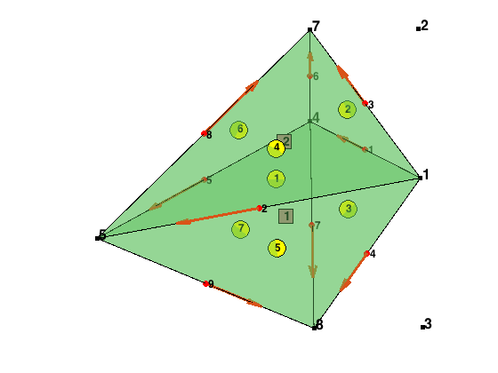
An Example
We show two tetrahedron with ascend ordering.
elem = [1 4 5 8; 1 4 5 7];
figure(1);clf;
showmesh3(node,elem);
view(-1,32);
findnode3(node,[1,2,3,4,5,7,8]);
findelem3(node,elem);
findedge(node,edge,'all','vec');
findelem(node,face);
snapnow;
display(edge); display(elem2edge);
display(face); display(elem2face);
display(elemSign);
display(elem2faceSign);
display(face2edgeSign);
edge =

           1           4
           1           5
           1           7
           1           8
           4           5
           4           7
           4           8
           5           7
           5           8


elem2edge =

           1           2           4           5           7           9
           1           2           3           5           6           8


face =

           1           4           5
           1           4           7
           1           4           8
           1           5           7
           1           5           8
           4           5           7
           4           5           8


elem2face =

           7           5           3           1
           6           4           2           1


elemSign =

    -1
     1


elem2faceSign =

     1    -1     1    -1


face2edgeSign =

     1    -1     1
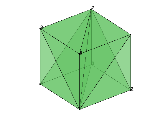
Boundary Faces and Boundary Conditions
We use bdFlag to record the boundary condition; see Data Structure: Boundary Conditions for details. For short, bdFlag has the same size with elem, and point to the boundary type of each local faces. If we change the ordering of elem, the corresponding local faces are changed. Threfore when we sort the elem, we should sort the bdFlag respectively. We use sortelem3 to sort elem and bdFlag at the same time. Note that sort(elem,2) sorts the elem only, and leave bdFlag unchanged.
[node,elem] = cubemesh([-1,1,-1,1,-1,1],2);
bdFlag = setboundary3(node,elem,'Dirichlet','x==1','Neumann','x~=1');
figure(2);clf;
showmesh3(node,elem);
display(elem); display(bdFlag);
findnode3(node,[1,2,3,4,5,7,8]);
[elem,bdFlag] = sortelem3(elem,bdFlag);
display(elem); display(bdFlag);
elem =

     1     2     3     7
     1     4     3     7
     1     5     6     7
     1     5     8     7
     1     2     6     7
     1     4     8     7


bdFlag =

    1    0    0    2
    2    0    0    2
    2    0    0    2
    2    0    0    2
    1    0    0    2
    2    0    0    2


elem =

     1     2     3     7
     1     3     4     7
     1     5     6     7
     1     5     7     8
     1     2     6     7
     1     4     7     8


bdFlag =

    1    0    0    2
    2    0    0    2
    2    0    0    2
    2    0    2    0
    1    0    0    2
    2    0    2    0
We can use bdFlag to find the boundary nodes, edges and faces. To find the outwords normal direction of the boundary face, we need the help of the gradbasis3. In the output of gradbasis3, Dlambda(t,:,k) is the gradient of . Therefore the outward normal direction of the kth face can be obtained by -Dlambda(t,:,k) which is independent of the ordering and orientation.
Dlambda = gradbasis3(node,elem);
T = auxstructure3(elem);
elem2face = T.elem2face;
face = T.face;
NF = size(face,1);
if ~isempty(bdFlag)
    % Find Dirchelt boundary faces and nodes
    isBdFace = false(NF,1);
    isBdFace(elem2face(bdFlag(:,1) == 1,1)) = true;
    isBdFace(elem2face(bdFlag(:,2) == 1,2)) = true;
    isBdFace(elem2face(bdFlag(:,3) == 1,3)) = true;
    isBdFace(elem2face(bdFlag(:,4) == 1,4)) = true;
    DirichletFace = face(isBdFace,:);
    % Find outwards normal direction of Neumann boundary faces
    bdFaceOutDirec = zeros(NF,3);
    bdFaceOutDirec(elem2face(bdFlag(:,1) == 2,1),:) = -Dlambda(bdFlag(:,1) == 2,:,1);
    bdFaceOutDirec(elem2face(bdFlag(:,2) == 2,2),:) = -Dlambda(bdFlag(:,2) == 2,:,2);
    bdFaceOutDirec(elem2face(bdFlag(:,3) == 2,3),:) = -Dlambda(bdFlag(:,3) == 2,:,3);
    bdFaceOutDirec(elem2face(bdFlag(:,4) == 2,4),:) = -Dlambda(bdFlag(:,4) == 2,:,4);
end
% normalize the boundary face outwards direction
vl = sqrt(dot(bdFaceOutDirec,bdFaceOutDirec,2));
idx = (vl==0);
NeumannFace = face(~idx,:);
bdFaceOutDirec(idx,:) = [];
vl(idx) = [];
bdFaceOutDirec = bdFaceOutDirec./[vl vl vl];

display(DirichletFace);
display(NeumannFace);
display(bdFaceOutDirec);
DirichletFace =

           2           3           7
           2           6           7


NeumannFace =

           1           2           3
           1           2           6
           1           3           4
           1           4           8
           1           5           6
           1           5           8
           3           4           7
           4           7           8
           5           6           7
           5           7           8


bdFaceOutDirec =

     0     0    -1
     0    -1     0
     0     0    -1
    -1     0     0
     0    -1     0
    -1     0     0
     0     1     0
     0     1     0
     0     0     1
     0     0     1